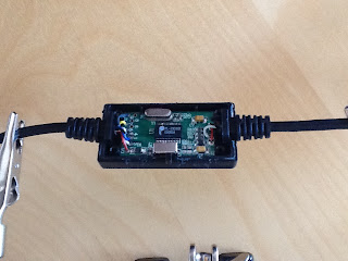
remember the arduino on hte stripboard ?! this phone cable supposed to do the usb-serial communication ?
yeah well both did not work. but I found out why.
First I most likely bricked my MCU by setting the wrong fuses.
Second I bricked all the following mcu's as well. At least it was only one...
So once that stack of bricked atmegas gets to big I'll dive into those fuse doctor shields. Not yet. More mcu's are awaiting their death by trial and error.
Mittwoch, 3. Oktober 2012
Samstag, 29. September 2012
Old mobile phone cable to TTL serial cable
Having not much success with uploading sketches to my DIY arduino I found this Article on the web. I unearthed an old Sony-Ericsson phone cable out of my wonder-cable-box. Its from a company called World Phone. Never heard of it but it has the Prolific PL2303HX chip on it. I cracked it open and tried to get the pinout. Sadly the board is not very well labled and the cables only had numbers on it. Except the GND and Vcc cables.
With the multimeter I messured the following data.
First I took White as TxD and Blue as RxD. Tried it on the board with the Arduino IDE, setting it to Uno, right com-port and programmer but no success. Famous avrdude: stk500_getsync(): not in sync: resp=0x00. Changed the settings to Duemilanove and other Programmers but again nothing.
I heard that hitting the reset button directly after the IDE states the Byte size of the compiled sketch should help, but not here.
I guess I have to wait until my retail Arduino board ships in.
My first arduino clone (serious soldering ever)
While reading my electronic shop catalogue and looking at the price tag I often think...
Hey I can do this myself while simultaneously ...
...save money,
...burn a lot of idle time,
...and of course, learn stuff I don't actually need in my daily life.
So I came upon Arduinos and building them by your own.
After searching the internets I finally stumbled upon this schematic design.
Sensational ! A topic just right up my street.
So I went on collection the stuff needed. Just bought some serious composition from the electronic dealer of my confidence. I must admit I am totally new to electronics and stuff. Anyways, got the stuff together, heated up the iron and started on a brainless soldering venture.
After putting together all the parts and wires I realized there is no LED in the schematic so after getting a LITTLE into it, I figured out (I hope at least) where to put that cool clear green led. And of course the led on pin13. After figuring out that I messed up gnd and + and fixing it, here it is.
As I said, compared to the schematic from the link. I also put in two leds and one ICSP port. I guess thats the way it is called. The ICSP port is haywired carefully into the board without touching any other cords. This article by barttech over at instructables.com showed me what to do.
With an STK500 and AVR Studio 4 I burned the bootloader onto the chip and transfered the ic after that back on my homemade arduino. Through the ICSP I wanted to upload sketches to it but it didn't worked out.
To be continued...
Hey I can do this myself while simultaneously ...
...save money,
...burn a lot of idle time,
...and of course, learn stuff I don't actually need in my daily life.
So I came upon Arduinos and building them by your own.
After searching the internets I finally stumbled upon this schematic design.
Sensational ! A topic just right up my street.
So I went on collection the stuff needed. Just bought some serious composition from the electronic dealer of my confidence. I must admit I am totally new to electronics and stuff. Anyways, got the stuff together, heated up the iron and started on a brainless soldering venture.
After putting together all the parts and wires I realized there is no LED in the schematic so after getting a LITTLE into it, I figured out (I hope at least) where to put that cool clear green led. And of course the led on pin13. After figuring out that I messed up gnd and + and fixing it, here it is.
 |
| stripduino with pinout for programming |
As I said, compared to the schematic from the link. I also put in two leds and one ICSP port. I guess thats the way it is called. The ICSP port is haywired carefully into the board without touching any other cords. This article by barttech over at instructables.com showed me what to do.
With an STK500 and AVR Studio 4 I burned the bootloader onto the chip and transfered the ic after that back on my homemade arduino. Through the ICSP I wanted to upload sketches to it but it didn't worked out.
To be continued...
Abonnieren
Kommentare (Atom)

